Medical Ultrasound Imaging
Friday, 17 May 2024
Info Sheets Out- side     | 'Frequency' p4 Searchterm 'Frequency' found in 161 articles 10 terms [ • ] - 151 definitions [• ] Result Pages : •
Ultrasound waves are created at harmonics of the delivered frequency.
Subharmonic imaging uses the harmonic oscillation of a system at a frequency that is a simple fraction of its fundamental frequency. The subharmonic response frequencies has half of the fundamental frequency.
The second subharmonic has a half fundamental frequency of one half the frequency, and so on.
See also Harmonic Imaging and Superharmonic Imaging. •
A transducer is a device, usually electrical or electronic, that converts one type of energy to another. Most transducers are either sensors or actuators. A transducer (also called probe) is a main part of the ultrasound machine. The transducer sends ultrasound waves into the body and receives the echoes produced by the waves when it is placed on or over the body part being imaged. Ultrasound transducers are made from crystals with piezoelectric properties. This material vibrates at a resonant frequency, when an alternating electric current is applied. The vibration is transmitted into the tissue in short bursts. The speed of transmission within most soft tissues is 1540 m/s, producing a transit time of 6.5 ms/cm. Because the velocity of ultrasound waves is constant, the time taken for the wave to return to the transducer can be used to determine the depth of the object causing the reflection. The waves will be reflected when they encounter a boundary between two tissues of different density (e.g. soft tissue and bone) and return to the transducer. Conversely, the crystals emit electrical currents when sound or pressure waves hit them (piezoelectric effect). The same crystals can be used to send and receive sound waves; the probe then acts as a receiver, converting mechanical energy back into an electric signal which is used to display an image. A sound absorbing substance eliminates back reflections from the probe itself, and an acoustic lens focuses the emitted sound waves. Then, the received signal gets processed by software to an image which is displayed at a monitor. Transducer heads may contain one or more crystal elements. In multi-element probes, each crystal has its own circuit. The advantage is that the ultrasound beam can be controlled by changing the timing in which each element gets pulsed. Especially for cardiac ultrasound it is important to steer the beam. Usually, several different transducer types are available to select the appropriate one for optimal imaging. Probes are formed in many shapes and sizes. The shape of the probe determines its field of view. Transducers are described in megahertz (MHz) indicating their sound wave frequency. The frequency of emitted sound waves determines how deep the sound beam penetrates and the resolution of the image. Most transducers are only able to emit one frequency because the piezoelectric ceramic or crystals within it have a certain inherent frequency, but multi-frequency probes are also available. See also Blanking Distance, Damping, Maximum Response Axis, Omnidirectional, and Huygens Principle. Further Reading: News & More:
• 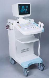 From SIUI Inc.;
'The CTS-310B is designed for the diagnosis of liver, gall, kidney, pancreas, thyroid, breast, uterus, bladder, ovary, etc. It is a versatile ultrasound scanner with both linear array scanning and convex scanning.' Features: 'Powerful image processing circuit & High quality image A wide range of probes for selection Cineloop Probe frequency conversation option Computer image communication Various measuring function Backlit keyboard'
Device Information and Specification
APPLICATIONS
See description above
CONFIGURATION
Normal system, 10' high resolution monitor, dual probe connector
Linear and convex
PROBES STANDARD
2.5MHz to 10.0MHz, linear and convex, broad band, trifrequency
IMAGING OPTIONS
Multi zoom rate and depth shift
OPTIONAL PACKAGE
POWER REQUIREMENT
AC 220V/110V, 50Hz/60Hz
POWER CONSUMPTION
0.1 KVA
•
Higher frequencies are attenuated by tissue more than lower frequencies. This means that the higher the frequency the lower the depth of penetration but the greater the resolution. Harmonic imaging allows the use of a lower frequency pulse to be picked up and sampled at the second harmonic (higher frequency) where the low frequency allows greater penetration and high frequency provides better resolution. See also Skinline. • 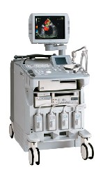 From ALOKA Co., Ltd.;
'A Platform for Pure Harmonic Detection Harmonic Echo™ technology constructs images using second harmonic components, which contain far less artifacts and noise than fundamental-frequency components. Pure Harmonic Detection is a technology to transmit distortion-free, fundamental-frequency ultrasound beams. And when the fundamental-frequency ultrasound beam is a pure sinusoidal wave, both the fundamental-frequency image and the Harmonic Echo™ image are much clearer with less noise. This technology is especially effective for obese patients and in a variety technically difficult scanning conditions.' Result Pages : | Share This Page Look Ups |
Medical-Ultrasound-Imaging.com
former US-TIP.com
Member of SoftWays' Medical Imaging Group - MR-TIP • Radiology TIP • Medical-Ultrasound-Imaging
Copyright © 2008 - 2024 SoftWays. All rights reserved.
Terms of Use | Privacy Policy | Advertise With Us
former US-TIP.com
Member of SoftWays' Medical Imaging Group - MR-TIP • Radiology TIP • Medical-Ultrasound-Imaging
Copyright © 2008 - 2024 SoftWays. All rights reserved.
Terms of Use | Privacy Policy | Advertise With Us
[last update: 2023-11-06 01:42:00]