Medical Ultrasound Imaging
Wednesday, 8 May 2024
Info Sheets Out- side     | 'Beamforming' Searchterm 'Beamforming' found in 9 articles 1 term [ • ] - 8 definitions [• ] Result Pages : • Beamforming
The wider the ultrasound beam, the more severe the problem with volume averaging and the beam-width artifact, to avoid this, the ultrasound beam can be shaped with lenses.
Different possibilities to focus the beam:
•
Mechanical focusing is performed by placing an acoustic lens on the surface of the transducer or using a transducer with a concave face.
•
Electronic focusing uses multiple phased array (annular or linear) elements, sequentially fired to focus the beam.
Conventional multi-element transducers are electronically focused in order to minimize beam width. This transducer type can be focused electronically only along the long axis of the probe where there are multiple elements, along the short axis (elevation axis) are conventional transducers only one element wide. Electronic focusing in any axis requires multiple transducer elements arrayed along that axis. Short axis focusing of conventional multi-element transducers requires an acoustic lens which has a fixed focal length. For operation at frequencies at or even above 10 MHz, quantization noise reduces contrast resolution. Digital beamforming gives better control over time delay quantization errors. In digital beamformers the delay accuracy is improved, thus allowing higher frequency operation. In analog beamformers, delay accuracy is in the order of 20 ns. Phased beamformers are suitable to handle linear phased arrays and are used for sector formats such as required in cardiography to improve image quality. Beamforming in ultrasound instruments for medical imaging uses analog delay lines. The signal from each individual element is delayed in order to steer the beam in the desired direction and focuses the beam. The receive beamformer tracks the depth and focuses the receive beam as the depth increases for each transmitted pulse. The receive aperture increase with depth. The lateral resolution is constant with depth, and decreases the sensitivity to aberrations in the imaged tissue. A requirement for dynamic control of the used elements is given. Since often a weighting function (apodization) is used for side lobe reduction, the element weights also have to be dynamically updated with depth. See also Huygens Principle. • 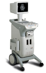 From Medison Co.,Ltd.;
'The Ultimate Black & White Ultrasound System. Redefining the standard of excellence in digital B/W ultrasound. Medison, the innovator in medical science, proudly introduces the ultimate evolution in black-and-white ultrasound system - the 128 BW. With its revolutionary responsive imaging technology, powered by Medison's harmonic imaging and digital 128 channel beamforming, 128 BW produces crystal-clear images in fraction of time. Designed and committed for excellent performance, 128 BW guarantees its scientific breakthrough results.' •
The earliest introduction of vascular ultrasound contrast agents (USCA) was by Gramiak and Shah in 1968, when they injected agitated saline into the ascending aorta and cardiac chambers during echocardiographic to opacify the left heart chamber. Strong echoes were produced within the heart, due to the acoustic mismatch between free air microbubbles in the saline and the surrounding blood.
•
In 1880 the Curie brothers discovered the piezoelectric effect in quartz. Converse piezoelectricity was mathematically deduced from fundamental thermodynamic principles by Lippmann in 1881.
•
In 1917, Paul Langevin (France) and his coworkers developed an underwater sonar system (called hydrophone) that uses the piezoelectric effect to detect submarines through echo location.
•
In 1935, the first RADAR system was produced by the British physicist Robert Watson-Wat. Also about 1935, developments began with the objective to use ultrasonic power therapeutically, utilizing its heating and disruptive effects on living tissues. In 1936, Siemens markets the first ultrasonic therapeutic machine, the Sonostat.
•
Shortly after the World War II, researchers began to explore medical diagnostic capabilities of ultrasound. Karl Theo Dussik (Austria) attempted to locate the cerebral ventricles by measuring the transmission of ultrasound beam through the skull. Other researchers try to use ultrasound to detect gallstones, breast masses, and tumors. These first investigations were performed with A-mode.
•
Shortly after the World War II, researchers in Europe, the United States and Japan began to explore medical diagnostic capabilities of ultrasound. Karl Theo Dussik (Austria) attempted to locate the cerebral ventricles by measuring the transmission of ultrasound beam through the skull. Other researchers, e.g. George Ludwig (United States) tried to use ultrasound to detect gallstones, breast masses, and tumors. This first experimentally investigations were performed with A-mode. Ultrasound pioneers contributed innovations and important discoveries, for example the velocity of sound transmission in animal soft tissues with a mean value of 1540 m/sec (still in use today), and determined values of the optimal scanning frequency of the ultrasound transducer.
•
In the early 50`s the first B-mode images were obtained. Images were static, without gray-scale information in simple black and white and compound technique. Carl Hellmuth Hertz and Inge Edler (Sweden) made in 1953 the first scan of heart activity. Ian Donald and Colleagues (Scotland) were specialized on obstetric and gynecologic ultrasound research. By continuous development it was possible to study pregnancy and diagnose possible complications.
•
After about 1960 two-dimensional compound procedures were developed. The applications in obstetric and gynecologic ultrasound boomed worldwide from the mid 60's with both, A-scan and B-scan equipment. In the late 60's B-mode ultrasonography replaced A-mode in wide parts.
•
In the 70's gray scale imaging became available and with progress of computer technique ultrasonic imaging gets better and faster.
•
•
In the 90's, high resolution scanners with digital beamforming, high transducer frequencies, multi-channel focus and broad-band transducer technology became state of the art. Optimized tissue contrast and improved diagnostic accuracy lead to an important role in breast imaging and cancer detection. Color Doppler and Duplex became available and sensitivity for low flow was continuously improved.
•
Actually, machines with advanced ultrasound system performance are equipped with realtime compound imaging, tissue harmonic imaging, contrast harmonic imaging, vascular assessment, matrix array transducers, pulse inversion imaging, 3D and 4D ultrasound with panoramic view.
•
The perfect image quality is dependent on some assumptions of the propagation of ultrasound waves in tissues after generating in an imaging system. These assumptions are important for the developing of optimal ultrasound imaging systems.
•
The propagation of ultrasound is straight ahead.
•
•
•
•
The amplitudes of the echoes are proportional to the difference of the acoustical impedance caused by different tissue layers.
See also Coded Excitation, Validation and Refraction Artifact, Q-Value, Ultrasound Phantom, Dead Zone, Narrow Bandwidth. Further Reading: News & More: •
The main lobe is the main acoustic transducer beam. There are other, smaller lobes called side lobes that are located around the main lobe. See also Side Lobe, Grating-lobe Artifact, Beam Steering, Beamforming. Result Pages : | Share This Page Look Ups |
Medical-Ultrasound-Imaging.com
former US-TIP.com
Member of SoftWays' Medical Imaging Group - MR-TIP • Radiology TIP • Medical-Ultrasound-Imaging
Copyright © 2008 - 2024 SoftWays. All rights reserved.
Terms of Use | Privacy Policy | Advertise With Us
former US-TIP.com
Member of SoftWays' Medical Imaging Group - MR-TIP • Radiology TIP • Medical-Ultrasound-Imaging
Copyright © 2008 - 2024 SoftWays. All rights reserved.
Terms of Use | Privacy Policy | Advertise With Us
[last update: 2023-11-06 01:42:00]